|
| BACKGROUND:
I have been building
and flying 144” Kawasaki KI-61 Toni’s since about 1980. My first was
powered by a Homelite 5.3 chainsaw that I bought and cut off all the parts until
it looked like an engine. It was a real shaker but it did fly the Toni well. Since
then I have had three of them over the years. It’s been several years since
I got rid of my last one and I was thinking about building another when I became
aware of the RCS215 5-cylinder gas radial engine. I had seen it fly in a Stearman,
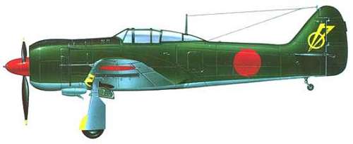
and it seemed the perfect choice for a large scale warbird. Near the end of WWII,
the Japanese were unable to obtain any more in-line engines for their KI-61’s
and had over 200 complete airframes with no engines just sitting on the ground.
The decision was made to covert the air frame to accommodate the Mitsubishi HA-112,
a 14-cylinder two-row radial and the KI-100 was born. |
| PLANS:
Over the last 20 years, my original shop drawings for
the KI-61 had either turned hard and yellow or disappeared. I thought the easiest
route to go would be to purchase some smaller plans and enlarge them. I bought
a few sets from various plan drawers and went to the expense of enlarging one
set up to the 144” size required. As I started to get ready to cut parts,
it became obvious that like most hand drawn plans; the parts would never fit correctly,
especially when enlarged by 25%. It was going to require a lot of tweaking, cutting,
sanding, and guessing to get things right. I do a lot of scratch building and
this has always been a problem. I had recently completed
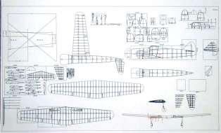
a 132” Vulcan Bomber from my own plans that I had drawn in AutoCad. I was
extremely pleased with them because everything fit like a glove when I cut out
the parts. Thus, I decided to bite the bullet and draw my own for the KI-100.
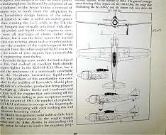
Using three views from a 1977 Arco Publication and a Hasegawa plastic model kit,
I set out to draw up a set. It is fairly easy to draw the three views, but that
doesn’t give you the fuse former profiles. To get those, I assembled the
plastic model fuse and then cut through it at the former locations to get a former
plan. Then I enlarge it on a copier to a size that allows me to measure it out
and transfer it to AutoCad. 43 hours of drawing time later, I had the plans done. |
| | |
| Reference book |
3-View reference |
Cad drawing |
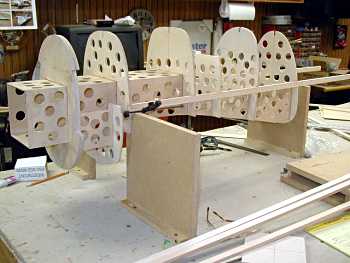
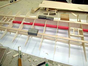
| CONSTRUCTION: Step 1-Fuse
I decided to begin construction on the fuse first, because I wanted
to get it framed to the point that I could start making the molds for the canopy
and the cowl early in the project. This would allow me to work on them piecemeal
as framing construction went along rather that have to stop everything for 2-3
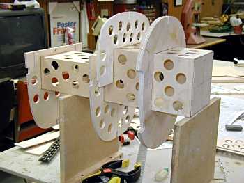
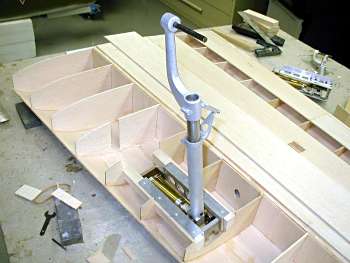
weeks while I made the molds. I decided to built the fuse
around the engine box and add the remainder of the fuse on a crutch. After cutting
all the fuse parts, I found that as I had imagined, the use of AutoCad enabled
the parts to fit together so well that I was able to completely assemble the fuse
with out any glue what so ever. This allowed me to verify that everything would
line up true, before gluing. |
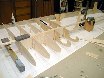
| |
| Engine box |
Engine box and wing saddle |
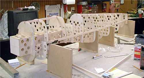 |
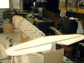
| Complete fuse |
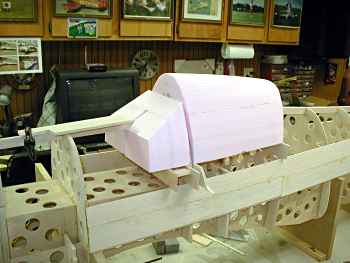
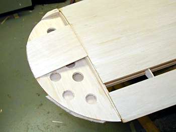
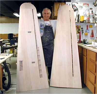
| CONSTRUCTION: Step 2-Canopy molds
Since no canopies are available for this airframe, I will have to
vacuum form my own. Since the largest plug that I can get into my over is about
15” land and the finished canopy is nearly 30” long I will have to make
it in two pieces.
The hardest part of that process is the
making of a good mold. It is very time consuming with a lot of waiting time for
things to dry. This is why I wanted to be able to work at it as the project went
along. The process that I use is as follows: 1 .Hot wire the basic
shapes out of pink insulation foam.
2. Temporarily fix them to the fuse and
sand to the final shape.
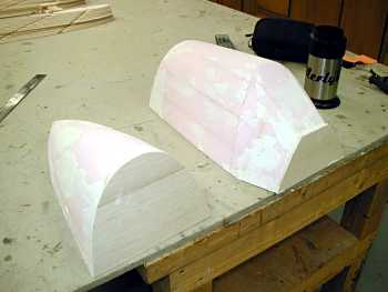
3. Fill with drywall joint compound and sand smooth.
4. Add balsa end caps to make them over size and additional caps to change
any undercuts so that the mold will come out of the finished canopy.
5. Fiber
glass with 1.4 oz cloth. Prime and seal until you have a glass smooth finish.
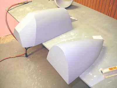
6. Make a female mold plug out of Ultra-Cal 30 plaster. This is done by laying
on a 1/8” thick layer of Ultra-Cal. After it has set up, apply fiber drywall
tape and more Ultra-Cal until you have 3/8” to ½” built up so
it is strong enough that it won’t crack as you handle it. Remove the plug
from the Ultra-Cal mold. After it has completely cured, sand out any imperfections.
It is difficult to sand so it is important that you have a really good plug to
start with. Then prime it with a filler-primer and 400 wet sand it.
7. Wax
the inside of the Ultra-Call mold and then fill it with Durham’s Rock Hard
Water Putty. I like this product because after you pull it from the Ulta-Call
mold and it has cured (7-10 Days depending on the size of the plug) you can final
sand it as it isn’t as hard as the Ultra-Cal.
8, Once you have sanded
it out it is ready for vacuum forming.
9. I use 0.040 PETG plastic for all
my canopies. Some times I use 0.060 if the pull gets too thin.
10. The secret
to getting a really clear final canopy is to pull one canopy on the mold. Then
remove it, trim all the ragged stuff off and wet sand it with 400 wet/dry sandpaper.
Then put it back on the plug and pull another over it. This way it comes out like
clear glass. |
| |
| Front canopy section being cut and
sanded | Rough plugs filled for sanding prior
to fiber glassing |
|
| Plugs ready for first casting |
| CONSTRUCTION:
Step 3-Hortizonal stab and elevators
Since the stab has
a symmetrical airfoil, you have several choices for alignment. Usually I glue
on little legs to each rib and then build it over the plans. This time I decided
to cut the ribs in half and build them on a flat sheet of 1/8” balsa. You
actually have to cut out a 1/8” thick piece from the center of each rib to
compensate for the balsa center. 1. After gluing the ribs onto the
sheet, add the upper spar.
2. Sheet with 1/8” balsa. Turn it over and
add the lower spar and sheet the bottom.
3. Add the leading edge and sand
to shape.
4. Cut out the elevators, add hinge blocks and cap off the edge
with ¼” and 3/8” balsa.
5. I use functional boost tabs on
the elevators to minimize flutter, so cut those out and finish the edges.
6. I run the leading edges of the elevators and boost tabs through the band saw
at the proper angle and then hinge them.
7. Fiberglass it and it is ready
for gluing to the when the fuse is complete |
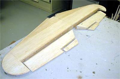
| |
| Top half of stab |
Sheeted stab |
|
| Glassed stab, elevators, and boost tabs |
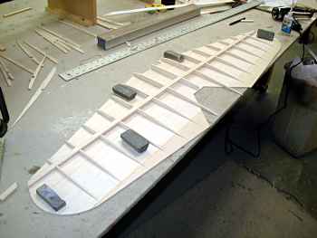
| CONSTRUCTION:
Step 4-Wing
1. I begin wings by gluing legs to each
rib to align the center lines.
2. I set up the root, tip, and a center wing
on the plans with the top spar in place. When everything is in alignment I glue
the top spar to the root and tip ribs. I always built a wing upside down so that
I can add servo mounts, retract rails, etc. before removing the wing from the
bench.
3. Another advantage of drawing your own plans is that you can set
your rib spacing anyway you want to. I decided on a 4” spacing which would
give me 17 ribs in each half. Since I buy all my balsa from Lone Star, the sheets
are oversized. This allows me to rip them to exactly 4” for use as shear
webs. I like to build a box spar as it is extremely strong. Using 3/8” x
¾” balsa spars I glue in each rib while adding the front and rear
shear webs. This keeps everything at right angles and automatically puts each
rib at the proper location.
4. I cut the shear web between the root and rib#2
at a five degree angle and this sets my dihedral.
5. Next I add the servo
rails and tube for servo wires and retract plumbing. I have my local hobby store
save the 1” tubes that K&S metal sends their music wire and brass tubing
in for use in the fuse and wings.
6. Add the rear spars
7. Sheet the
top of the trailing edge and the bottom of the wing from the front spar to the
rear spar.
8. Add landing gear blocks. For an airplane of this size, I use
Annco retracts. The first set that I bought back in 1980 lasted through all three
of my Ki-61’s. They are still available from Ed Cochran at E&J Hobbies.
9. Sheet the bottom from the front spar to the leading edge.
10. Remove
the wing from the plans and sheet the top.
11. Add leading edges and sand
round.
12. Add wing tips.
13. Cut out the ailerons, and flaps, finish
and hinge them.
14. When I build a box spar I use a ½” thick
plywood dihedral brace that sides through ribs 1 and 2 between the top and bottom
spars.
15. Join the wing, fiberglass the center with 6 oz cloth, and then
cover the wing with 1.4 oz. cloth |
BACK to PROJECTS
|
|
Become an RCWarbrids site supporter by making a donation.
|
$5.00 |
 |
$10.00 |
|
$15.00 |
|
$20.00 |
|
| |
|
|
|
|